HAVE QUESTIONS? ASK PHIL

Have questions about CAD, Fusion 360, or the Portland maker scene? Ask Phil! He’s a Principal Software Engineer at Autodesk, inc. and teaches CAD at Portland Community College. He’s also the host of Community Conversations series: Getting started with 3D modeling in Fusion 360

You can reach him at phil.eichmiller@autodesk.com

Phil Eichmiller — Principal Software Engineer at Autodesk, Inc.

TUTORIAL: How to use ultra realistic Quixel Mixer materials with Fusion 360 [Part 2]

Welcome back! In Part 2, we’ll explore adding Quixel Materials to your designs in Fusion 360 and setting up a rendering scene. If you haven’t already, review Part 1 and install Quixel Mixer. You’ll want to create and export a mix for use in Fusion 360 prior to the steps in this tutorial, or download an example material set here.

First, let’s create a new project in Fusion 360:

  1. Creating a new Fusion 360 Project

After you open Fusion 360, Click “Save” and give your project a name. In this example I used “QuixelMaterialDemo.”

After you save your project, we’ll want to create a new component and make it active.

2. Create a new Component

This is generally a good practice with Fusion 360, because we can more easily manage changes made to the design when the timeline is broken up by individual component histories. Name your component “Floor” and then make sure “Activate” is selected (should be by default), click “OK” to continue.

Next, we’ll want to create a sketch to define the floor’s dimensions. Click “Create” and make a Center Rectangle on the bottom plane.

3. Create a Floor

Make your sketch 3 meters x 3 meters in size, with the Origin at the center. Click “Finish Sketch” to continue. If you’ve done everything right, then you should have a sketch that is fully constrained (i.e., you’ll see black lines instead of blue lines for the outer dimensions of your sketch).

Next, we’ll extrude the sketch below the plain. This will create a new body, based on our sketch dimensions.

Click Create and then Extrude. Then, extrude the sketch -1mm below the plane and click “OK.”

Next, Save the design. You’ve created your first body and now would be a good time to save your progress.

Note the reason for your save and Click “OK.”

Next, we’ll want to change the Appearance of our floor. Click Modify Appearance to bring up the Appearance Window.

4. Add material

Here we can see the default material for the Floor body. We’ll want to replace that material with our Quixel Mix. To do that, let’s start by downloading a similar material.

Note: in general, you’ll find it is easier to add Quixel Mixer materials when you adapt an existing material in Fusion 360 with similar attributes. In this case, we can use the existing Asphalt Material.

After the download finishes, click and drag the Asphalt material into your design.

We can then replace the default material with the Asphalt.

5. Replace Fusion 360 Material with Quixel Mix

Next, we can begin modifying the Fusion 360 Asphalt material with the Quixel Mix.

As mentioned in Part I, the materials in Fusion 360 are made up of individual map image files:

Albedo/Diffusion/Color — the color a material reflects

Normal and/or Height Maps — the bumps and imperfections along a surface

Roughness — the smoothness of a surface (ranging from a sharp reflection to fuzzy/diffuse)

Reflectance/Specular/Metalness — the reflectiveness of a surface (ranging from mirror finish to a dull surface)

Anisotropy/Ambient Occlusion — the shadows along a surface

Refractive —how light bends through a surface

Emissive — how much light a surface emits (glow)

Translucency/Opacity — how transparent a surface is to light

If you’re using the included sample images, you’ll find some but not all of these maps. Depending on what materials you’re mixing, you’ll need different image maps. The sample image package includes:

Floor_Diffuse.png — Color (placed in Parameters)

Floor_Roughness.png — Roughness (placed in Parameters)

Floor_Specular.png — Reflectance (placed in Parameters)

Floor_Normal.png — Normal (placed in Relief Pattern (Bump))

Floor_AO.png — Anisotropy (placed in Advanced Highlight Controls)

By replacing and adding these map files to the Fusion 360 Asphalt material, you can transform it to the Quixel mix. To start this replacement process, open the Appearance window, double-click the Asphalt material and then click “Advanced…”

Rename the material to “Quixel_Asphalt” to distinguish the material from the original Fusion 360 Asphalt.

Under Parameters, we can add three (3) image maps. First, we’ll apply the diffusion/color map to the Image input in Fusion 360. Click on the Image filename 1_mats_surface_asphalt_color.jpg and navigate to your replacement images.

Select your Albedo/Color/Diffuse map file. If you’re using the sample images, it’s the file named Floor_Diffuse.png. Click Open to replace the default image file.

Next, we’ll repeat the process with the Reflectance and Roughness maps. By default, these two material attributes are set as Slider values, click the drop down arrow and then select Image to replace the slider value with an image map.

Next, select the Metallic/Specular image map if you’re using the sample images, select Floor_Specular.png and click Open.

Next, repeat the same steps for the Roughness value. Select Image and then select your Roughness Map. If you’re using the sample images, select the Floor_Roughness.png.

Now that we’ve completed the three Parameter maps, we can move on to the Relief Pattern (Bump) map. Once again, we’ll replace the default image file (1_mats_surface_asphalt_.jpg) associated with the material. Note: Fusion 360 supports both bump and normal maps. If you want to know more about these two approaches to texturing a 3D model, then click here.

Next, we need to change the Relief Pattern from a Height Map to a Normal Map. To do this, we need to Edit the image.

Next, scroll down to Advanced and change Data Type to Normal Map.

Next, we need to ensure that all of our maps are using the same Sample Size. Be sure to repeat this step for all image maps. We also need to ensure that all of our Maps have Linked texture transforms. Check the Link texture transforms under the Transforms section of the Texture Editor. Be sure to repeat this step for all image maps.

These steps are important, because they ensure that all of the image map data are aligned equally to the material in Fusion 360. After you’ve verified these settings, you can click “OK” to finalize the changes to this material.

Now that the material has been updated you can Close the Appearances window.

To check and validate our new material, we need to switch to the Render Workspace in Fusion 360. Click on the Workspace button, and change it from DESIGN to RENDER.

6. Test render scene

Next, let’s save the design to capture the new material settings in your Fusion 360 Timeline. Click File and Save.

Fusion 360 will prompt you to describe your save point. Let’s name this save “Quixel Material Added” and click OK.

Before we can test our new material, we need to edit the SCENE SETTINGS from the SETUP Menu. Open the SCENE SETTING Window and Click+Drag “Dry lake bed” to the Current Environment and then Click Close.

We also need to change the IN-CANVAS RENDER settings to FAST, so that we can easily see the material’s performance during rendering. To do this, click on the IN-CANVAS RENDER SETTINGS icon and Click on the Fast tab. Then, Click OK to update the rendering method.

Next, we can preview the rendering, and see how the various maps work together under different lighting conditions. To do this, start the In-Canvas Rendering and then open Scene Settings, click on the Position Icon to bring up the Rotation and Scale Sliders. By changing the rotation, you can see how the surface of your floor object casts shadows at different angles, corresponding to the surface material.

Make sure to save your project to retain your rendering settings. If you’ve made it this far, then congratulations! You now have all of the information necessary to import Quixel Mixer materials in Fusion 360. In Part 3, we’ll explore some techniques for applying these materials to complex geometries, and how to post-process your images for additional realness. In Part 4, we’ll take these realistic models and generate Augmented Reality experiences for iOS.

Stay tuned!

Week 2: Summer Internship

This week I continued working on 3D asset creation. My basic approach so far has been to start with a simplified geometry from Fusion 360, then export that design as an .FBX (Autodesk Maya file format), import the FBX to Blender for UV mapping, material, and motion rigging. There’s probably a more streamline way to generate this content, but from a feasibility standpoint, this approach allows me to be flexible and to use different tools for discrete tasks. This week I will be importing these combined assets into Unreal Engine.

This week was also my final week for the term at PCC, where I have enrolled in their online course for Advanced Fusion 360. I’ve been working on a group project, and designing assemblies for use in a solar projector system. The design is based on COTS (commercial off-the-self parts), which required me to draft profiles to meet engineering specifications.

Picatinny rail specification downloaded from wiki-commons.

Picatinny rail specification downloaded from wiki-commons.

The final deliverables are due this coming Saturday, and there is still a good bit of work to be done before we get graded on this project. Nevertheless, I am very pleased with the current state of things. I’ve been using Quixel Mixer to produce more realistic rendering material than the library included with Fusion 360. I say, “more” realistic because Fusion 360 already has some excellent materials. Take a look at this rendering of a Bushnell 10x42 monocle (one of the components in this project):

Bushnell Legend 10x42 Ultra HD Tactical Monocular Black rendering v14.png

I haven’t yet added any details, but as you can see, the rubberized exterior and textured plastic hardware are fairly convincing. Now, take a look at the mounting hardware rendered with Quixel textures:

Picatinny rail bracket rendering v7.png

An important component in photorealism is the inclusion of flaws. Real life objects are never perfectly clean, perfectly smooth, or with perfect edges. Surface defects, dirt, scratches, and optical effects play an important role in tricking the eye into believing a rendering. With Quixel Mixer, it is possible to quickly generate customized materials. While this product is intended for use with Unreal Engine and other real-time applications, it does an amazing job when coupled with a physical based renderer.

Picatinny rail set with hardware and bracket.

Picatinny rail set with hardware and bracket.

I’m excited to see what can be done with these materials in a real-time engine, especially given the advanced features of Unreal Engine 5. Fusion 360’s rendering is CPU driven, whereas Unreal is GPU accelerated. With both Nvidia and AMD now selling GPUs with built-in raytracing support, it won’t be long before we see applications that offer simultaneous photorealism rendering within modeling workflows.

Additionally, GPUs also work extremely well as massively parallel computing units, ideal for physical simulations. This opens up all kinds of possibilities for real-time simulated stress testing and destructive testing. It wasn’t that long ago that that ASCI Red was the pinnacle of physical simulation via supercomputer. Today, comparable systems can be purchased for less than $2,000.

Of course, this price assumes you can buy the hardware retail. The current chip shortage has inflated prices more than 200% above MSRP. Fortunately, with crypto markets in decline and businesses reopening as vaccination rates exceed 50% in some regions, there are rays of hope for raytracing-capable hardware being in hand soon.

Week 1: Summer internship

This week I kicked off an internship with Astrea Media. We began with a general meeting via zoom, with each intern and staff member introducing themselves. I’ll be generating some 3D content for an exciting new project and so far the work is going well. This is not my first experience working with a realtime engine. I’ve done some work in Unity, but never to a polished degree. Our team is working with similar technologies, and I’m eager to learn more about this process.

This week I began optimizations for an existing 3D model. I discovered several hindrances to efficient rendering: absurdly high poly-count, textures in needlessly large image format, non-solid mesh geometry, etc. Rather attempting to rework this model, I instead decided to explore a new design. Due to the organic shapes for this asset, I decided to use Fusion 360’s Sculpt workspace. The sculpt workspace enables designers to create complex shapes with smooth surfaces (e.g., car bodies). There are a few trade-offs to this approach:

  • Non-parametric design

    • Sculpt bodies are based on t-splines (I’ll say more about this later), and do not offer design history/timeline functions

  • Symmetry functions

  • Rapid mesh generation

  • Efficient generation organic shapes

  • T-splines

    • 3D modeling is achieved through a variety of mathematical models for defining shapes. T-splines allow for the creation of freeform surfaces that are defined by a matrix of control points. While meshes tend to be defined by triangles, t-splines work best when all faces are defined by 4 vertices (T-shapes and rectangles).

This last point is important.

Screen Shot 2021-05-30 at 21.19.24.png

This sphere seems like a perfectly logical shape. Indeed, if you click “FINISH FORM” in the upper right corner, Fusion will compute this body and create a solid. Seems simple, right? There’s just one problem: the top of that sphere contains faces with only 3 vertices. As mentioned earlier, t-splines work best when faces are made of 4 vertices. The sphere computes just fine, but as soon as you begin to manipulate this shape, there’s a very good chance that all of those converging 3-point faces at the top and bottom will begin overlapping each other. For example, see what happens when I attempt to apply symmetry to this shape:

Screen Shot 2021-05-30 at 21.51.47.png

Instead of maintaining the converging vertices, the solver calculated something like the iris on a camera.

To avoid problems like this, there’s another option: quadballs.

Screen Shot 2021-05-30 at 22.03.43.png

As you can see, this sphere doesn’t have the same aggressive converging vertices as the other model. The advantage here is that each face can also be split diagonally, efficiently creating triangle mesh faces with minimal distortion.

Screen Shot 2021-05-30 at 22.09.32.png

When exporting this geometry for use in a realtime engine, the mesh conversion produces a high-fidelity representation of the t-spline body, preserving shape details.

Kinetic-friendly spoon project Mega Post

That’s a wrap! It’s certainly been an interesting semester, but now I am ready to put it behind me. Reflecting on the spoon project, I have some final thoughts and observations. First, I want to thank the fine folks at CMU School of Design. From the amazing and hardworking faculty and graduate student cohort, I have had nothing less than inspiration and encouragement throughout this entire process, despite the obvious challenges of working remotely.

Rendering of sixth and final (?) spoon design. I pulled the kitchen design (Pierre Gilles) and bowl (Damogran Labs) from GrabCad.com. The spoon and coffee mug are mine.

Rendering of sixth and final (?) spoon design. I pulled the kitchen design (Pierre Gilles) and bowl (Damogran Labs) from GrabCad.com. The spoon and coffee mug are mine.

This project was divided into two parts: the first part focused on exploring different ways of prototyping and making. This was described to me as an informal way of A/B Testing for methods. The second part involved the deliberate iteration of prototypes through user testing — a challenge in the context of a global pandemic and social distancing. To make the most meaningful design choices possible given limited resources, I decided to leverage the power of physical simulation to supplement the making of physical prototypes.

There are a variety of 3D software tools that offer some degree of physical simulation. For this project, I selected Maxon Cinema 4D R20 (Educational License) and Blender as my two ways of making. I chose these because I already am familiar with Cinema 4D and understand know how to manage a workflow in that context, because Blender is open source and free for anyone to use, and both programs work under MacOS and Windows environments (my rendering workstation is a Hackintosh with multiple operating systems, which grants the flexibility to overcome certain technical limitations). My initial experiments with Cinema 4D were… not great.

My very first (and failed) attempt to simulate fluids in Cinema 4D. Carnegie Mellon University School of Design Prototyping for Interaction Spring 2020

As you can see, there are “physics” happening here, but they are not anything close to the physics of the real world. This is not “real world” physics, this is Asshole Physics:

Zachary "Spokker Jones" Gutierrez and I came up with the term "Asshole Physics" when we were discussing the game and the physics models it employed. Basically there's a lot of crap you can knock over and kick around, including dead bodies, buckets, cans, and little sections of drywall which are standing around in the middle of rooms for no obvious reason. Zachary casually mentioned, "I have made it a point to knock over every fucking thing in that game. I am living out my fantasies of being a giant asshole," and I responded by stealing his "asshole" comment and claiming that I made it up. Thus "Asshole Physics" was born.

Without more sophisticated plugins to simulate fluid, Cinema 4D R20 is only “out of the box” capable of non-newtonian semisolids. I can make stuff bump around and “squish.” I can have a 3D character micturating on the side of a building. I can create the appearance and illusion of something like a fluid, but with such restrictions, I could not realistically evaluate my spoon designs. I explored my options and found that Next Limit’s RealFlow plugin would meet my basic needs. Best of all, they offer a free 30-day trial! My initial excitement quickly waned after the plugin failed to install and activate on my system…

(This email chain is long and covers a week of back and forth with customer service. I am including the entire conversation as a way to recreate my experience. While this may not directly relate to the scope of this project, I still believe that there is value in documenting the unexpected problems that crop up when trying to do something new.)

Mail_02.png
Mail_03.png
Mail_04.png
Mail_05.png
Mail_06.png
Mail_07.png
Mail_08.png
Mail_09.png

It took a week to finally get everything sorted with the demo. During that time, I began to explore option B: Blender.

Blender is a free, powerful, open source 3D creation tool. Best of all, it includes the mantaflow fluid simulation engine (since version 2.8). I have worked with Cinema 4D on other projects, and have become fairly comfortable with the interface. Given my experience with Fusion 360, Inventor, and C4D, I knew that I would need to overcome a learning curve before I could use this software to meet my needs for this project. Fortunately, I was able to find a spectacular tutorial series for beginners.

If you want to read more about my experience with the tutorial, click here.

This tutorial was ideal because it involved exercises that helped me learn how to use the interface, and covered several different workflows. I was really impressed with Blender’s node-based material system and procedural textures. You can work stri…

This tutorial was ideal because it involved exercises that helped me learn how to use the interface, and covered several different workflows. I was really impressed with Blender’s node-based material system and procedural textures. You can work strictly with parametric modeling, or you can discretely modify mesh geometry to create highly organic and imperfect forms. I’m excited to work with Blender on future projects. It’s a very exciting time to be working in 3D.

While working through these tutorials, I began sketching and working in Fusion 360 to craft my first spoon designs for part 2 of this project. You can read more about this experience here.

Takeaways from Part 1

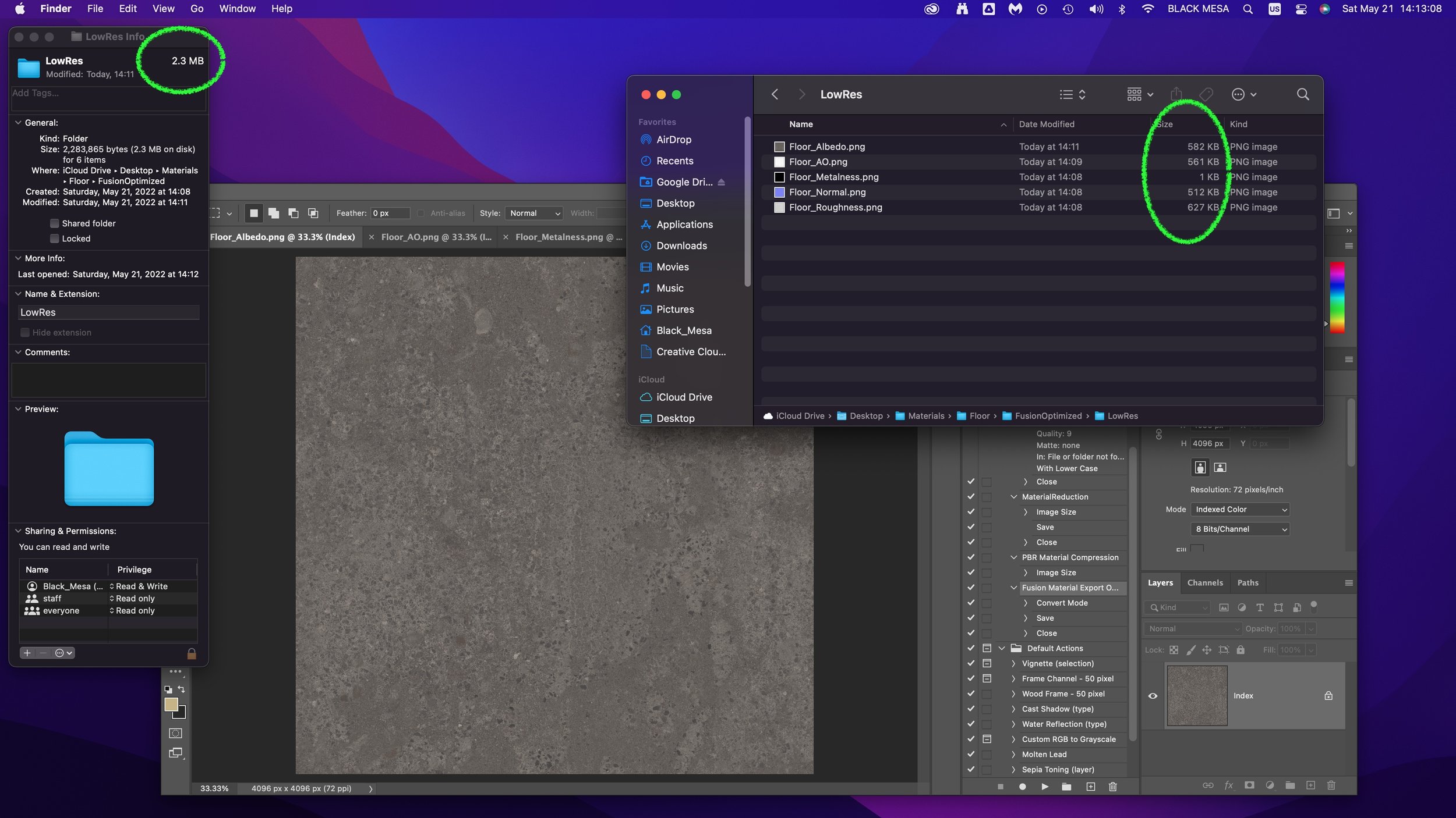
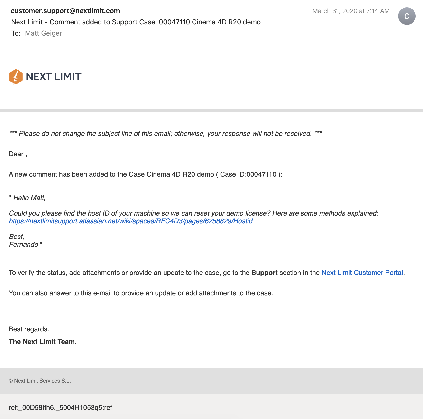
I really appreciated the responsiveness from the team at Next Limit. Clearly there are problems with the software’s implementation of their product’s copy protection. This is an all-too-common problem in the world of software. Programmers gotta eat just like everybody else, and we certainly should make sure that the talented and hardworking folks behind the code are able to put food on their table at the end of the day. Piracy can deprive a small business of the necessary revenue to keep the lights on, so I am absolutely sympathetic to this reality and what risks are involved when you release your software for demo purposes. Getting people to pay for something that they can easily get for free is a challenging proposition. At the same time, you cannot realistically expect to get customers to pay for software if they cannot try it first. Ultimately, this one week of back and forth with customer support was a critical loss. I never completed a side-by-side comparison of fluid simulations. While I did eventually succeed at installing and using RealFlow to do fluid simulations, (and was honestly impressed with how easy it was) I did not, however, have enough time to setup a comparable simulation to evaluate spoon designs. My trial expired about a week ago, and I see this aspect of the project as a lost opportunity. If Next Limit applied similar licensing practices as Maxon (verify it through .edu email address), they could offer an educational package of their RealFlow plugin.

Blender really came through for me. The learning curve was aggressive, but not impossible. While I found mantaflow to be a respectable and entirely capable fluid simulator, it was not without its own share of issues. I spent a lot of time making granular tweaks to improve the fidelity of my simulations, while also using the observations from my simulations to inform design decisions for my spoons in part 2 of this project.

Part 2: Design Iterations Based on User Testing

While this project required user testing and design iterations based on feedback, I decided to limit the user evaluations to address handle shape and the spoon’s overall dimensions. This was not an arbitrary decision or an excuse to focus on physical simulation of fluid dynamics (with user testing as an aside). No, this decision was based on the nature of the course from which it was assigned: Prototyping for Interaction Design. This semester I have have been focusing on designing for interaction (arguably, all designers do, at some point in their process, focus on this aspect). When thinking about the tools we use (to eat food) as a system, it is important to consider the touchpoints involved. The handle of a spoon is a non-trivial component. It can take on many forms, and naturally includes affordances. How someone holds a spoon, and how easy it is for them to use it are central to the evaluation of the design.

The iterations of design were highly generative in nature, inspired by both user evaluations and physical simulations, I maintained a homeomorphic continuity: treating the initial shape as an elastic form to be molded and reshaped to maximize performance. Knowing how a concave shape might be optimized to perform under rapid movement — I wanted to create something that would be useful, and the physical simulation of fluids facilitated a means of evaluation — is only one aspect of a more complicated interaction, and this test alone could not fully address human needs. When physical form is designed and directed to improve user interaction (and physical properties are given equal consideration), it is possible to create a truly useful tool. I realize that this is a very technical description, but it is easier to understand when properly visualized. I have rendered a compilation sequence to show how this spoon shape evolved to its final(?) form (I am still considering a physical prototyping stage for this project over the summer).

A sequence of fluid dynamics tests designed to evaluate fluid retention of concave forms. Carnegie Mellon University, School of Design, Prototyping for Interaction, Spring 2020.

Toward the latter half of this sequence, you will notice a change in colors (for both the liquids and spoons). I decided to differentiate the final rendering sequences as these were based on user evaluations. The colors chose for these final sequences are based on the color tags used for the user test:

These printouts are derived from DXF vector images exported from Fusion 360. The designs shown are oldest (top) to newest (bottom). The fifth design (blue) is rendered with a blue body and green liquid.

These printouts are derived from DXF vector images exported from Fusion 360. The designs shown are oldest (top) to newest (bottom). The fifth design (blue) is rendered with a blue body and green liquid.

I printed and mailed the paper prototype to a potential user suffering from ongoing hand tremors (my partner’s mother). I sent this without written instructions. Instead, I only provided different color tags to facilitate feedback. My user let me know that the red spoon handle was in the “Goldilocks” zone in terms of size and shape: not too big, not too small, not too curvy, not too straight. Using this feedback I constructed the sixth and final (?) form — see the first image of this post.

The user test included a direct side-by-side comparison with existing dinnerware.

The user test included a direct side-by-side comparison with existing dinnerware.

Before developing these simplified paper prototypes, I also experimented with ways of making more three-dimensional forms that could be sent in the mail. While this novel approach showed some potential, I was concerned with how user error might complicate or (even worse) bias feedback. Still, these paper prototypes helped me to better understand and interpret the scale of my 3D models.

PaperPrototype_01.jpg

Final Thoughts

This project still feels somewhat incomplete. Perhaps this is because the generative design process itself can always demand further iteration, or maybe it is because I have not yet created a physical prototype that can actually be tested as an eating instrument. Maybe it is only because there were still a few “rogue droplets” (grrrrrr) that I simply could not keep contained with the completion of my sixth iteration. Whatever the net effect might be from these various shortcomings, I am pleased with the learning opportunities that were presented throughout this exploration of design.

Were I to continue with this process, the next steps would be to 3D print the latest shape using a food-safe material (there are a few third-party vendors that offer this service). I would then ship that latest design for further user evaluation. I believe that there are still many additional iterations necessary before I could defend having created something that satisfies the criteria I set out with this project (i.e., a spoon that overcomes the challenges of involuntary muscle movements and essential tremors).

If I were to collaborate with others, I would also want to evaluate the ecological and economic impact of such a device. How might we go about manufacturing to appropriate scale? How might additional user tests with a wider audience influence the existing form? There remains many unanswered questions and a newfound respect for the power of generative design.

Bugs in the Blender

I have continued to have luck exploring the Fluid simulations in Blender, but this process has not been without its quirks. I recently encountered a strange issue related to Particle Radius settings

Particle Radius

The radius of one liquid particle in grid cells units. This value describes how much area is covered by a particle and thus determines how much area around it can be considered as liquid. A greater radius will let particles cover more area. This will result in more grids cell being tagged as liquid instead of just being empty.

Whenever the simulation appears to leak or gain volume in an undesired, non physically accurate way it is a good idea to adjust this value. That is, when liquid seems to disappear this value needs to be increased. The inverse applies when too much liquid is being produced.

What does this look like in practice? My most recent simulation actually seems to produce fluid as the scene progresses.

Nevertheless, I was able to gain critical insights into this form and will continue to iterate new designs. This is being done in conjunction with paper prototyping. These forms are less sophisticated, but still provide valuable information about how users will experience and interact with this flatware.

SpoonPrototype.jpg

Spoonfuls of updates

This week was packed full of progress on multiple projects. I received feedback for my group’s birth control information app “MyGallery.” Our work was even featured on CMU’s Design page.

Crafting an iconographic representation for the withdrawal method was my proudest moment.

Crafting an iconographic representation for the withdrawal method was my proudest moment.

I’ve continued to explore fluid simulations with Blender. I’ve ran into some technical hurdles: Blender 2.82 uses a variety of protocols to leverage GPUs for rendering and computation. It offers an AI-driven denoiser (Optix), CUDA path tracing, and OpenCL. My MacBook Pro has an AMD Radeon Pro 5500M GPU as well as the option to plug in a Radeon Frontier Edition (first generation Vega) eGPU on Thunderbolt 3. Plenty of GPU compute power in either configuration, but there is a snag: MacOS 10.15 (Catalina) has deprecated OpenCL in favor of Metal 2+. CUDA and Optix are proprietary to nVidia GPUs. Apple hasn’t shipped a Mac with nVidia GPUs since Kepler launched (GeForce 700 series). Blender supports AMD ProRender, but I found it was terribly unstable.

I could easily slip into a tangent about how unfortunate the breakup between Apple and nVidia truly is, but I will spare you.

My current workflow involves queuing some tasks to my desktop, running Windows 10. The GPUs are dual Radeon VIIs. Unfortunately, I found that rendering on Blender is unstable when both GPUs render in parallel. No problem, since I can free up the other GPU for Folding@Home (a hobby of mine that has exploded in response to COVID-19). Who would have guessed that a global pandemic would boost a distributed computing project to exascale?

Despite these obstacles of platform compatibility, I have made significant progress on my simulation-based research. It is difficult to understate how exciting this project has been for me. For some context: the ASCI Red supercomputer (at the Sandia National Laboratories) was built in 1996, and was the fastest supercomputer in the world until 2000. It was the first computer to achieve true terascale computing (one trillion floating point operations per second). I built my first terascale computer in 2013. This was shortly after leaving my job at Intel. There was something very gratifying about building a computer with a CPU I helped manufacture. GLaDOS G4 (you can see the project here, scroll down to “Everything Else”) was built with a GeForce GTX 780 GPU and Intel Core i7 4770k overclocked to 4.5 GHz. It ran nearly silent and fit inside an up cycled Apple Power Mac G4 (microATX equivalent) case.

The ASCI Red supercomputer was designed to simulate nuclear weapons tests. Today, I am using a system roughly ten times more powerful to simulate soup spilling out of a spoon. I was inspired to approach this problem by two projects. The first was a 2013 project from Portland State University (my alma mater) to make a coffee cup for zero-gravity environments. they used drop cages and 3D printing to iterate several designs until they had a shape that held liquid. “It wasn’t needed, but it was requested.”

The other project hit me right in the heart.

The S’up Spoon is the embodiment of good design. The design was inspired by deep empathy for a user’s problem, and the solution involves as little design as possible. There are few technologies in this world that we trust enough to put in our mouths. If you can make it in this space, you can make it (almost) anywhere. During the fall semester, Moira and I visited the Carnegie Museum of Art. They had an exhibition on accessibility design, and I was brought to tears by stories of innovation and vibrant improvements to quality of life for people with disabilities. Technology, at its very best empowers people to realize their fullest potential. We can easily get lost in the exhilaration of the complex, but this impulse must not dampen our ability to appreciate the elegance of simplicity. Some problems are best solved by form. I saw many incredible solutions in that exhibition, but this spoon has really stuck with me.

My goal is not to make something better, but perhaps a little bit different. The shape of the S’up spoon is intuitive, and if we had never seen a spoon before, we might conclude that it is the better design over more traditional forms. It is however, under our current cultural context, a strange thing to behold. It looks more like a wizard’s pipe or a warrior’s horn. It is beautiful and ergonomic. I do not intend to elevate those specifications. Instead, my goal is to make a spoon that is inconspicuous while still achieving similar results for users who suffer from motor movement difficulties.

How has my first design faired under simulation?

While I can certainly see the appeal of a long hollow channel, I’ve become increasingly concerned with how this shape my be difficult to keep clean. I can imagine objects getting wedged toward the back depending on what is being consumed. I have began to work on a second iteration with a more shallow channel. Still, this first iteration does fairly well. It is managing to retain most of the 15ml (i.e., 1 tablespoon) of fluid under rapid movement.

I enjoyed this simulation so much that decided to make a rendering:

I have not yet gotten back into Cinema 4D to evaluate RealFlow. Despite the challenges regarding compatibility, I am truly impressed with how powerful this open source software has become with this latest release.

Now that I have established this workflow, I can easily switch out revised designs to test under identical conditions. I’m still not sold on the current handle shape, and I think I can improve liquid retention by tweaking the angle of the lips. The flat bottom (Chinese style spoon) does fairly well, with it’s obtuse angle walls. Next, I will try a concave structure with a wider base for the handle and a more aggressive descending angle.

Visual Communication Fundamentals Project: Anti-Affordances Video

Feels like forever since I’ve updated my blog. I have been learning to use Cinema 4D to create realistic 3D animations - it has been quite an adventure. I’ll be backdate posting some content about my process, but for now, I wanted to get this uploaded:


Gummi Bears

I’m spread pretty thin between projects, but wanted to post some new renderings. One of the benefits of Fusion 360 is the materials customization built into their rendering pipeline. And I think this project does a good job of highlighting this feature.

I’m kicking myself for not rendering at a higher resolution, but this lighting test did a fantastic job of demonstrating refraction with a slightly rough surface.

I’m kicking myself for not rendering at a higher resolution, but this lighting test did a fantastic job of demonstrating refraction with a slightly rough surface.

While the angle and lighting are more traditional (i.e., less creative) for a rendering shot, I’m including it because of the shadows and light transmittance between materials. This is the kind of thing that only looks convincing with ray tracing. R…

While the angle and lighting are more traditional (i.e., less creative) for a rendering shot, I’m including it because of the shadows and light transmittance between materials. This is the kind of thing that only looks convincing with ray tracing. Raster engines cannot accurately simulate light passing and reflecting off of materials like this.

I have a render running in the cloud right now for a scene with roughly 250 of these gummies piled on top of one another. With so many surfaces and ray transformations and generations coming from such a complex model, I cannot render it to useable resolutions locally. You can see the rest of my renderings and download the models for yourself on GrabCad.

Mac Mini 2018 in Fusion 360

This month cruised by fast. I have been spending the bulk of my time in Fusion 360, both for class projects, as well as personal exploration of the software. Here are some recent renderings:

Apple updated the Mac Mini last month, adding an optional 6-core Intel Coffee Lake (Core i7 8700B) processor configuration, Thunderbolt 3 (USB Type C interface), and a “Space Gray” makeover. using photos from Apple’s product page, I reconstructed th…

Apple updated the Mac Mini last month, adding an optional 6-core Intel Coffee Lake (Core i7 8700B) processor configuration, Thunderbolt 3 (USB Type C interface), and a “Space Gray” makeover. using photos from Apple’s product page, I reconstructed the IO layout and customized material and appearance settings. You can download my model here.

Opposite angle, to show off that sweet white LED!

Opposite angle, to show off that sweet white LED!

For anyone getting into CAD, I also recommend GrabCAD.com, where you can download (and contribute) 3D models for free! I was able to accelerate my workflow by downloading prebuilt models of the ethernet, USB, and HDMI ports.

A Robot Took Your Job

Last week I returned from my trip to Memphis (thanks, Andy! Hope Meara’s potty training is going well!) and I’ve been playing catchup ever since. I’m getting back into Fusion 360 with some more challenging projects. This week we covered how to use joints in assemblies. This is pretty wild stuff. You can download models from GrabCAD.com and upload them Fusion 360. It auto-magically converts models to work natively (with mixed results) in the work space. From there, you can define joints and move parts in real time! We did this in class using an industrial robot model. Of course, this meant the robots needed to fight…

Four robots go in, four robots come out. Because they are metal, and very strong, and even knives won’t kill them!!

Four robots go in, four robots come out. Because they are metal, and very strong, and even knives won’t kill them!!

This wasn’t the actual assignment. Instead we needed to create a render scene involving an earlier model from this class being assembled by robots. I was grinding away at this all day yesterday, and finally got around to rendering it. Because of the complexity of the scene, it’s taking quite some time to bake in all of those rays at HD+ resolution. Here’s the object being assembled for reference:

This is based on an existing design from a vinyl shelf I bought to keep my Laserdisc collection in prime display condition. I fantasized about having an actual product made for Laserdisc, and what that might look like. You gotta with red trim right?…

This is based on an existing design from a vinyl shelf I bought to keep my Laserdisc collection in prime display condition. I fantasized about having an actual product made for Laserdisc, and what that might look like. You gotta with red trim right? Because LASERS!!

Here’s a technical drawing, if you want to build your own. This will probably hold about 250 titles, based on my experience with my current shelf ( tweaked the dimensions to give it a bit more depth and room to breathe between stacks.

Here’s a technical drawing, if you want to build your own. This will probably hold about 250 titles, based on my experience with my current shelf ( tweaked the dimensions to give it a bit more depth and room to breathe between stacks.

i’ve been taking this class as an opportunity to not only learn the software, but also to push the limits of what the software can do. For me, this practice is like cartography. I’m mapping the borders by extending to the edge in all things. With this project, I wanted to not only torture test the rendering pipeline, but also test the limits of my beefy Hackintosh. As noted previously, my CPU appears to be the main bottleneck. But I wanted to see what it takes to exceed memory requirements. For this design and ray tracing session I’m utilizing ~25 GB of memory, and cooking my poor little quad-core Haswell® chip.

Nothing cooks like CAD! Note that the temperatures reflect a system with AIO liquid cooled CPU, and nine total fans, packed into an old PowerMac G4 case. Even when protein folding on both GPU and CPU, the system usually has a CPU core temperature ce…

Nothing cooks like CAD! Note that the temperatures reflect a system with AIO liquid cooled CPU, and nine total fans, packed into an old PowerMac G4 case. Even when protein folding on both GPU and CPU, the system usually has a CPU core temperature ceiling of about 70˚ C.

It’s been over four hours as of writing this, and the rendering has not yet reached “final” quality. Scene complexity is a huge factor in rendering time.