I have some exciting news! October 23rd, 2024, I was once again invited to guest lecture at CMU School of Design. I decided to follow up with a recorded version to share. In this recording, made after the original lecture session, I cover the essentials of 3D modeling with a focus on beginner-friendly techniques. You'll find practical insights into mesh modeling, workflow tips for Blender, and an introduction to preparing models for augmented reality. The full lecture video is embedded below, followed by detailed notes that offer a step-by-step breakdown of theory and techniques for anyone new to 3D design. Dive in, explore, and start building your own 3D modeling skills.
Principles of Mesh Modeling
Note on Mesh Modeling Focus—Or Why This Lecture Focused Primarily on Mesh Modeling:
Meshes are the standard 3D model type used in real-time 3D engines—like Unity, Unreal, and virtually every AAA video game title in the last 30 years, going all the way back to Quake, by id Software in 1996.
Key Principles:
Use Quad Faces Whenever Possible: Design your shape faces with quads instead of triangles and ngons.
Reason: Quads are infinitely divisible, making it easier to adjust geometry resolution as needed. Tris and Ngons are not as flexible, which can lead to undesirable artifacts and poor topology.
3D games primarily use triangles (tris) instead of quads because triangles are the simplest polygon shape and always planar (a flat surface), making them computationally faster to render in real-time on limited hardware, which was crucial for early gaming systems underpowered computer hardware. Essentially, triangles require less processing power to calculate and display on screen compared to quads, which have more vertices and edges.
On modern computer hardware we can get away with more complex geometry, and it's generally a better trade-off to build mesh models from quads. That is, the computational costs are vastly outweighed by the benefits of evenly divisible face geometry and more manageable topology. Lastly, quads are easily converted into tris, by producing diagonal edges between the four vertices.Work from the Lowest Possible Polygon Count: Always start with the lowest polygon count (i.e., resolution) for your model. You can increase resolution later with subdivision modifiers, but it's not as easy to reduce the resolution later.
Reason: Editing a high-resolution mesh is more difficult than working with a low-resolution one, which offers greater control and flexibility. It also takes much more processing power and memory, which will slow down Blender and increase the risk of crashes.Keep Base Shapes Simple: Keep your base shapes as simple as possible. When adding details, create those elements as separate objects. When you hit a milestone, consider duplicating a model or a collection of models to a new instance for further refinement.
Reason: This approach makes 3D modeling more manageable, allowing for easier adjustments and maintaining clean geometry.Use Modifiers and Non-Destructive Editing Whenever Practical: Designing a symmetrical shape? Cut it in half and use a Mirror Modifier to cut your editing time in half. Keep in mind that the most complex designs can ultimately be derived from very basic shapes: Spheres, Cones, Toruses, and Cubes.
Work From Reference Images, Even If Just A Few Basic Sketches: Press Shift + A to open the Add menu. Navigate to Image > Reference. Select the image file you want to use from your computer. The reference image will be added to your 3D Viewport, where you can position, scale, and rotate it as needed for your modeling task.
Build The Overall Form First, and Then Separate into Smaller Objects: This will ensure that your designs are cohesive and edges are properly aligned. When you're ready to divide into separate objects, duplicate the objects into a new Collection.
Experiment, Tinker, Explore, and Start Over: You're unlikely to get the design right on the first attempt. It's often necessary to work through the problem, and then start over from scratch once you've had enough time to explore the form. Reason: Your second draft will almost certainly be better than the first.
Blender Quality of Life Recommendations:
Save Your Project Files Early and Often: Use Blender's "Save Incremental" (⌥+⌘+S) (Option + Command + S) to manage version control. Doing this will give you the freedom to fearlessly tinker and explore (as mentioned in the previous point) before settling on a final design.
Crank Up The Number of Undo Steps: Open Edit from the top menu. Select Preferences to open the Blender Preferences window. In the Preferences window, click on the System tab. Scroll down to find theUndo Steps setting.
Increase the value (the default is 32). If you have enough system memory, set it to 256 for more flexibility in undoing actions. Close the Preferences window to save your changes.
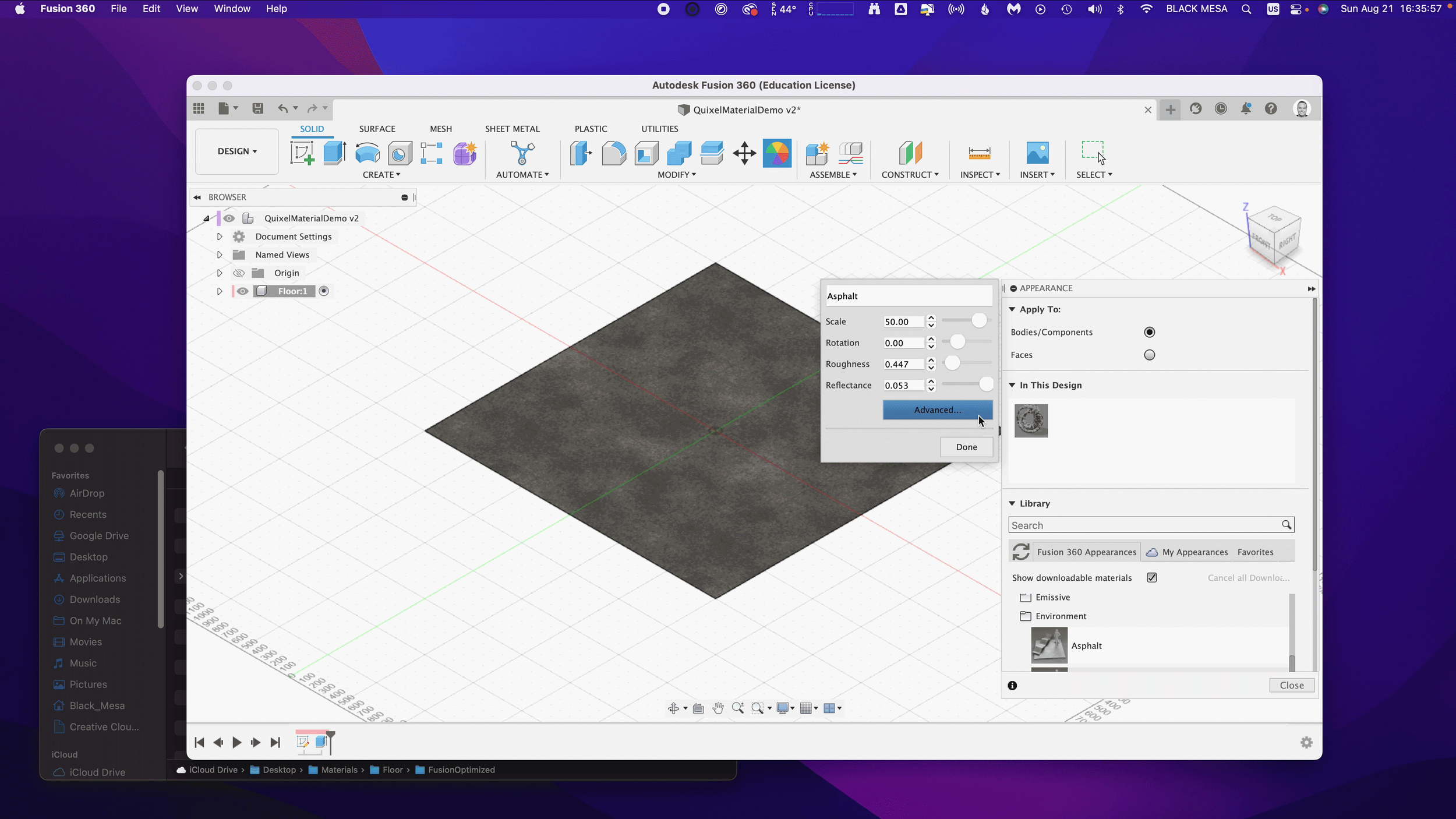
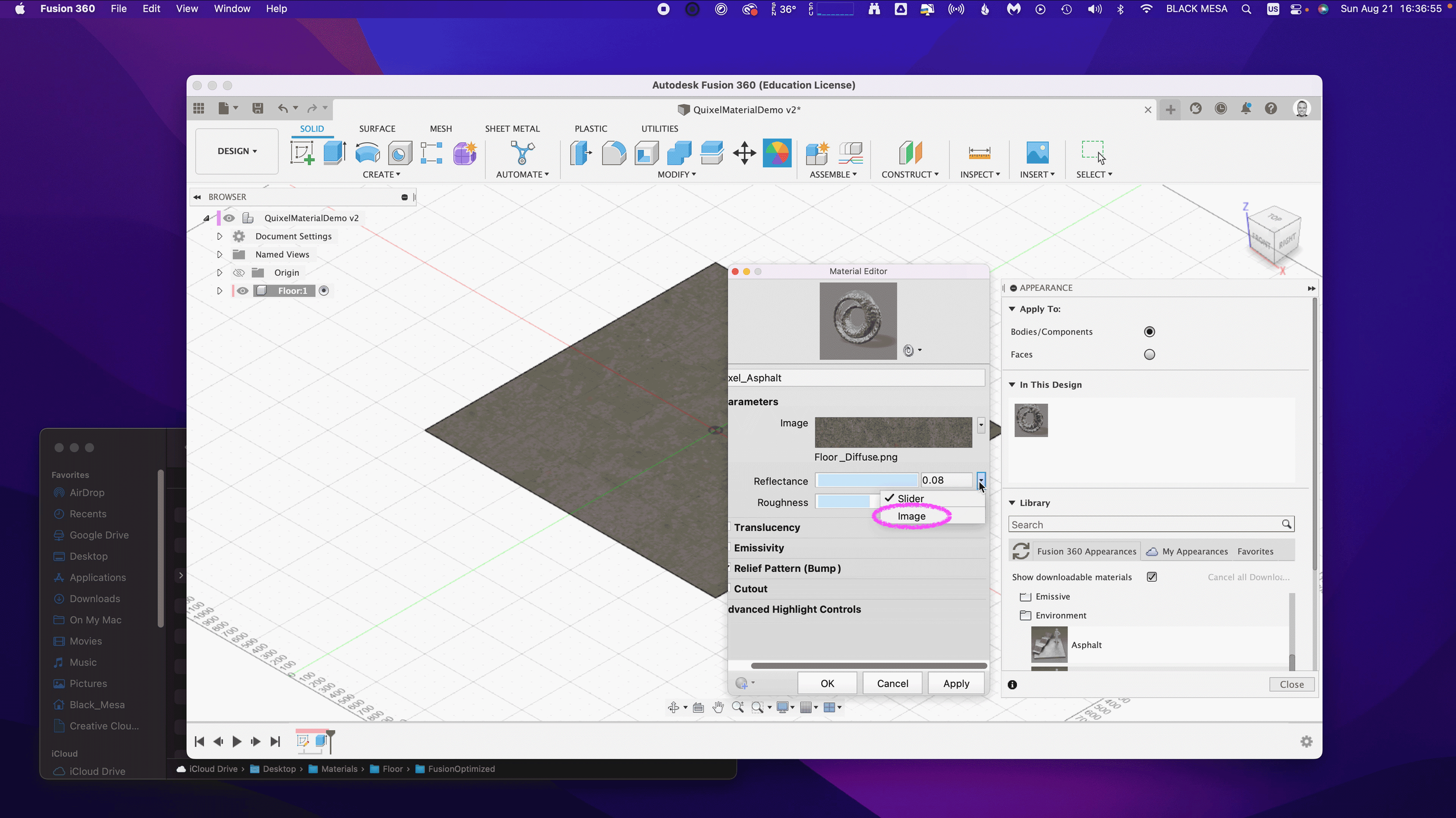
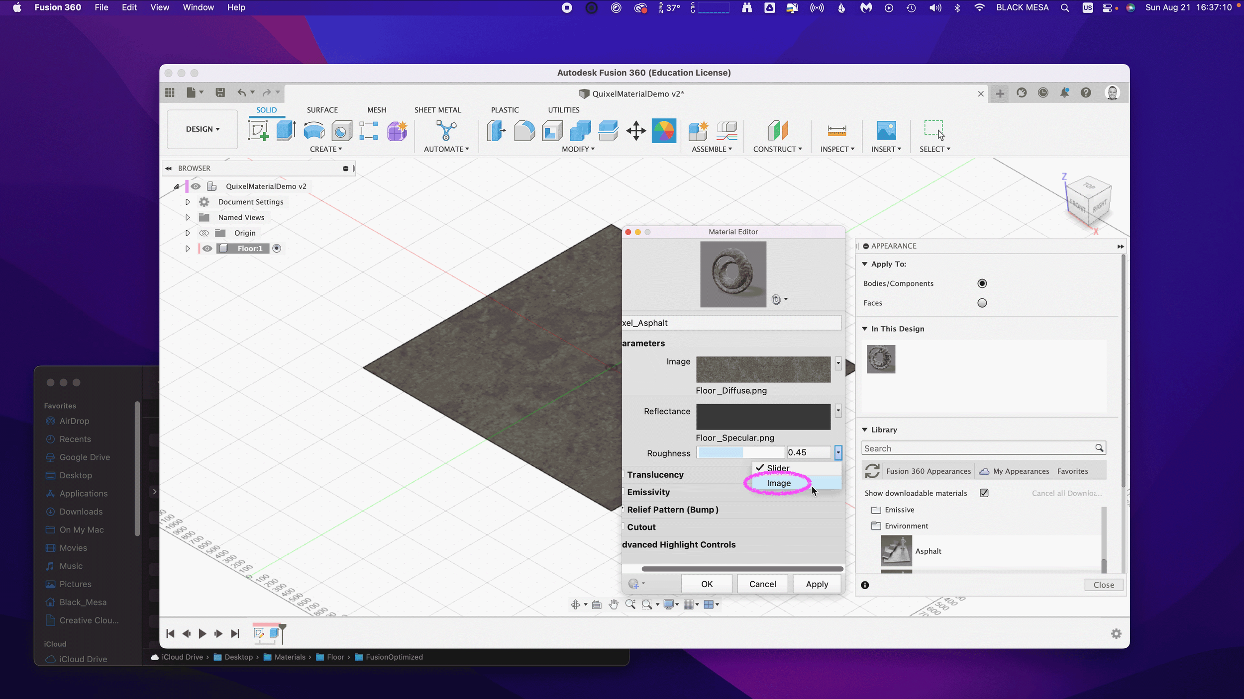
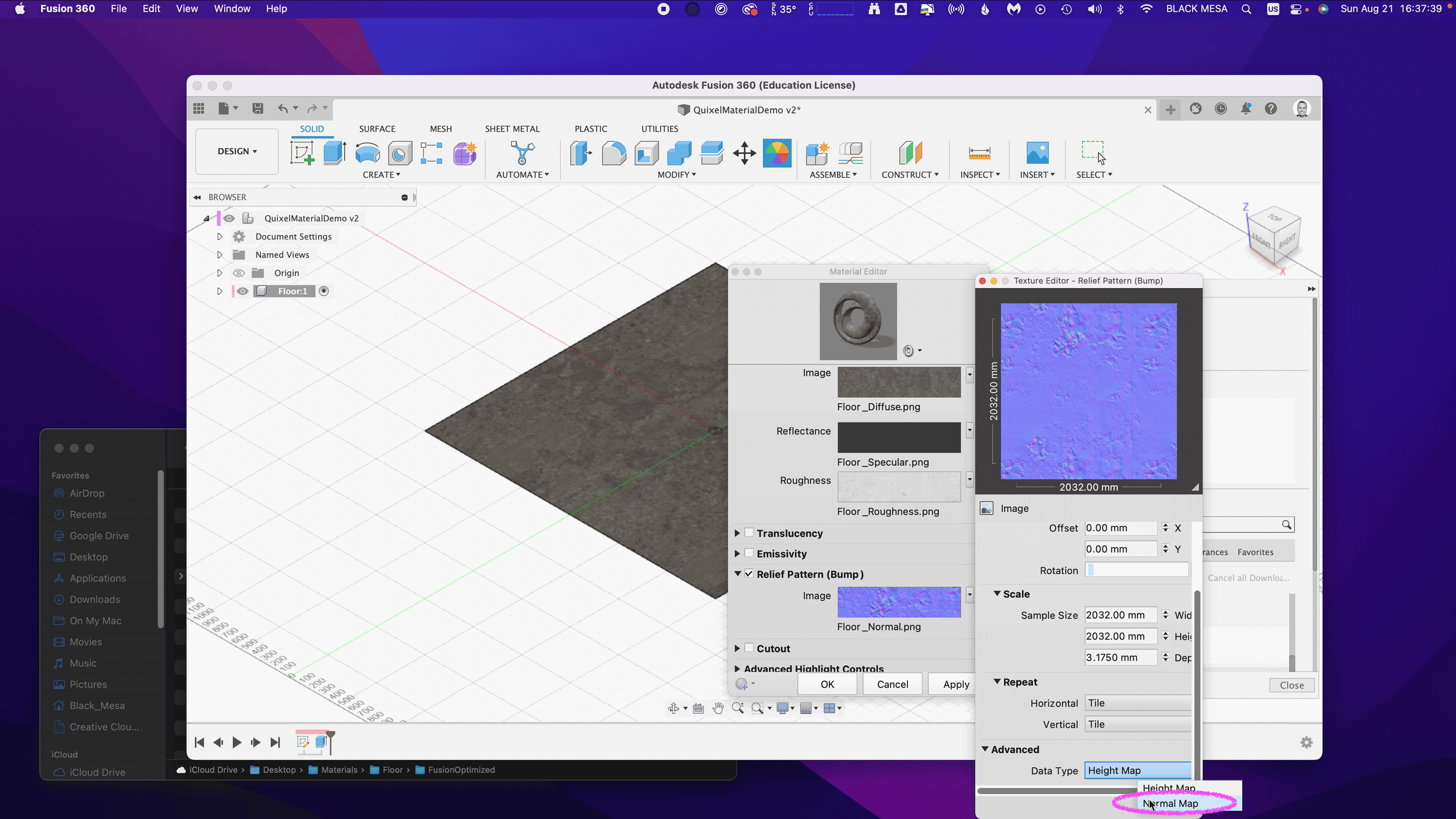
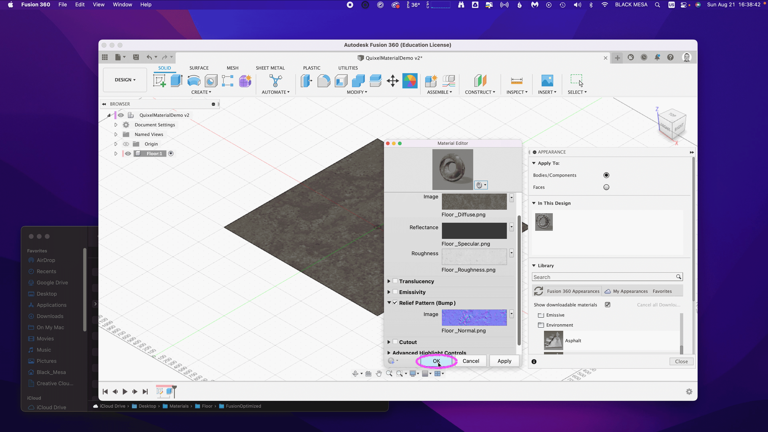
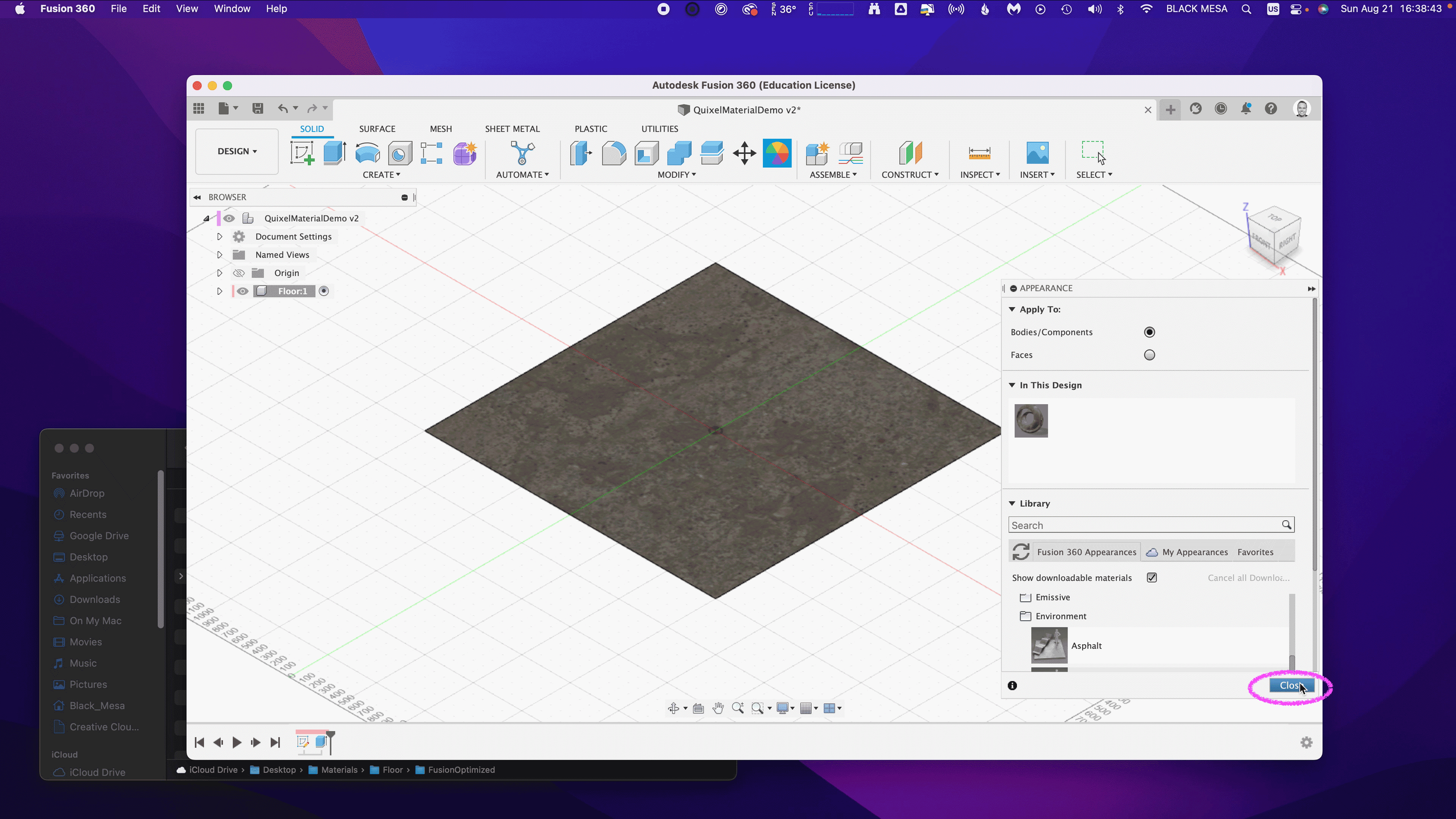
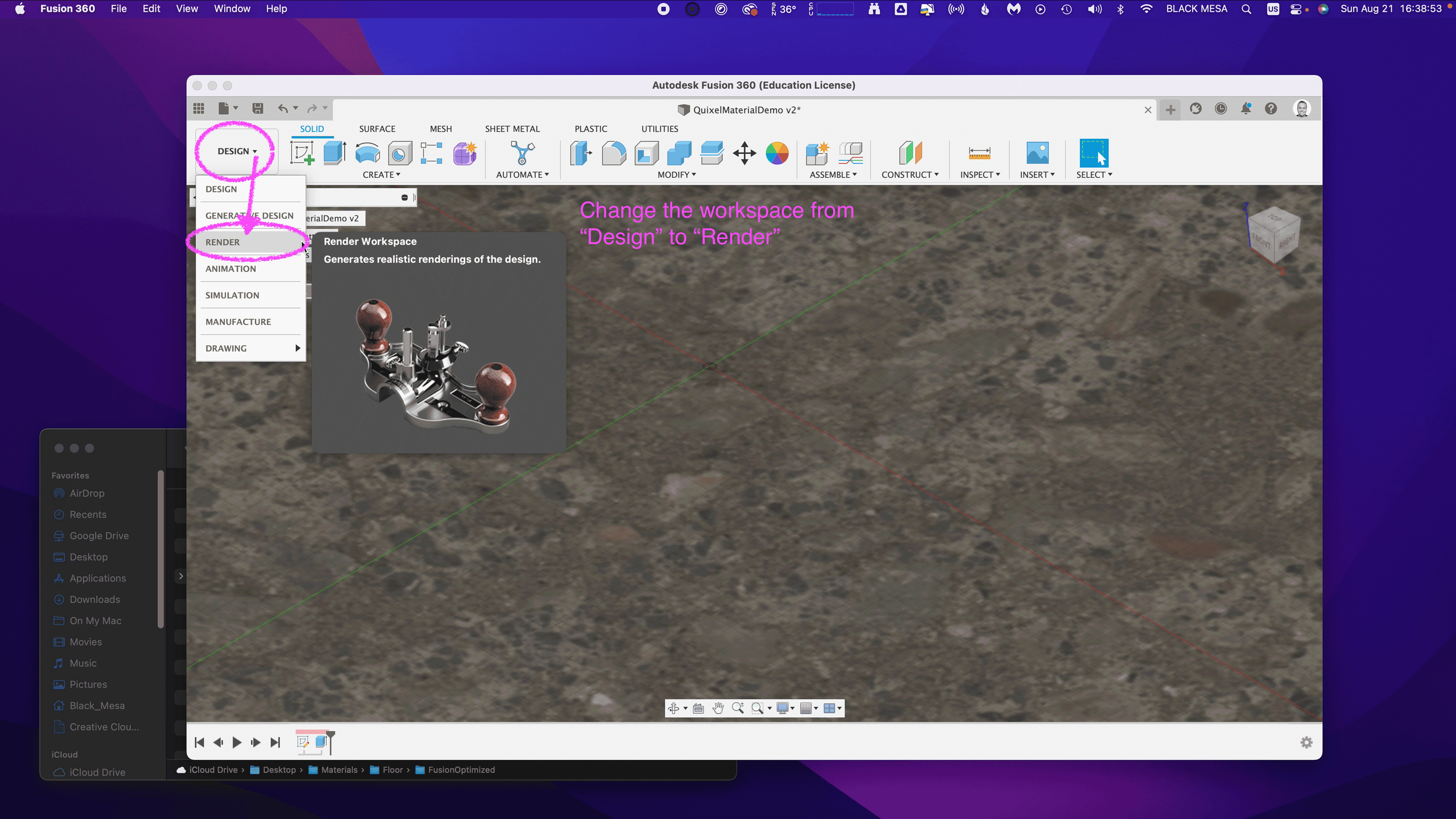
Consider Using A Material Library: Blender has a basic built-in material library, but it's not very useful. Look into large libraries, such as PBR Material Asset Library + OneClick Add-on for Blender (https://shardsofred.gumroad.com/l/CfOnY). Creative Commons License (CC0) materials can be used for basically anything, and will save you time.
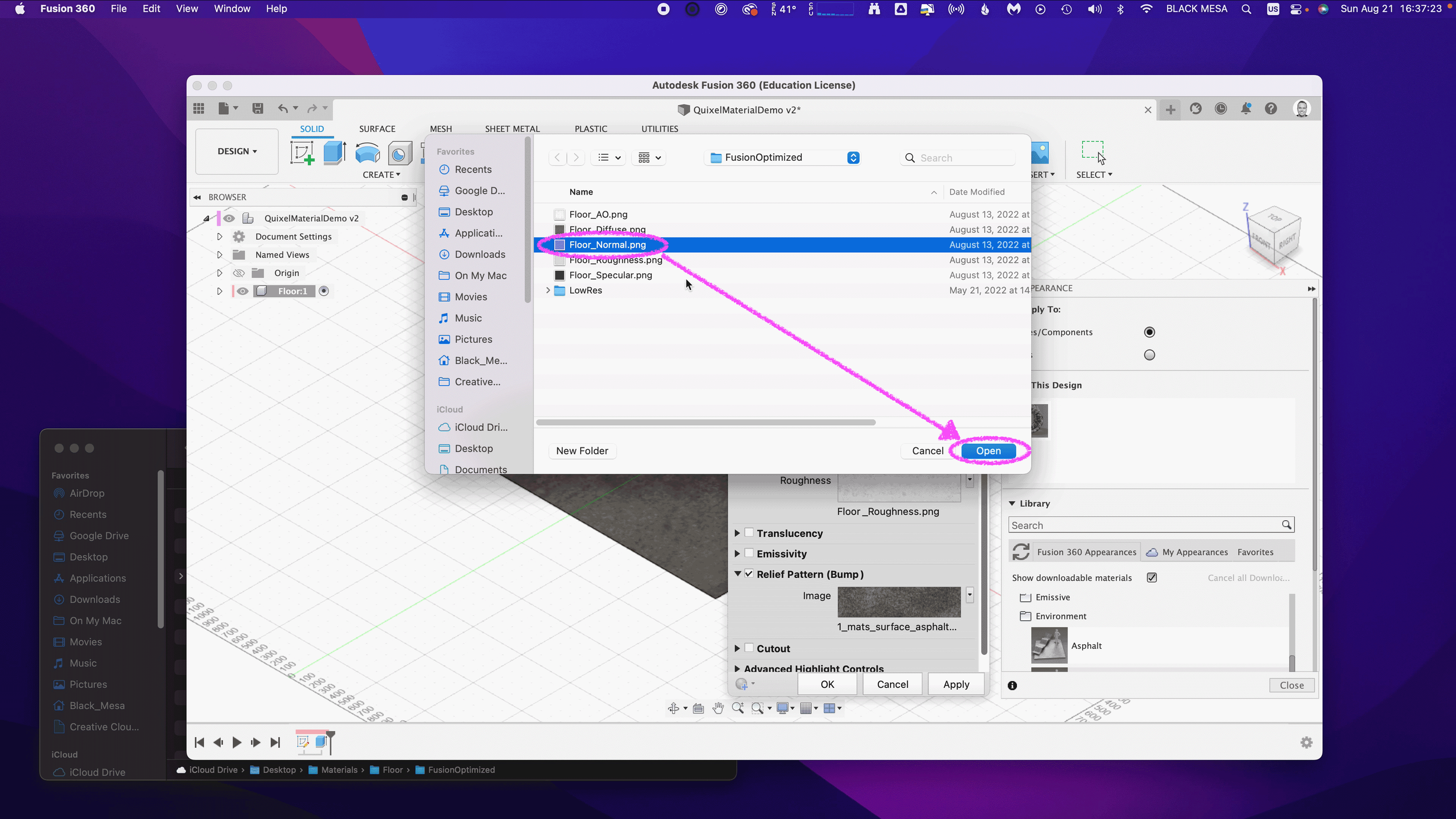
Remember to Perform a UV Unwrap on Your Model Geometry for Best Results When Texturing: The most realistic textures in the world won't help you if your model doesn't have good UV Mapping. Remember the chocolate Santa Claus example? Proper wrapping is essential for creating realism with your models. https://docs.blender.org/manual/en/latest/ modeling/meshes/uv/applying_image.html
Recommended Extensions and Add-ons:
VDM Brush Baker: Helps you create and bake Vector Displacement Maps directly in Blender.
Bool Tool: Boolean operations for complex shape creation.
Node Wrangler: Enhances node editing management.
Rigify: Automated rigging solution for character animation.
Loop Tools: Useful for organic modeling (with some bugs appearing
in Blender 4.2—be sure to keep this add-on updated!).
Other Useful Add-ons: Auto Mirror, F2, Extra Mesh/Curve Objects, Extra
Grease Pencil Tools, Copy Attributes Menu, and MeasureIt.
Bonus: Need furniture? Most of IKEA's catalog of products have 3D models available. Search for "IKEA" under Extensions and you can easily search and import 3D models into your scenes.
Note: Ensure 'Allow Online Access' is enabled in Blender's System Preferences for add-on updates.
Create Augmented Reality Experiences for iOS with Xcode Developer Tools, Reality Composer, and USDZ File Format
Once you've finalized your form, added necessary details, and applied your materials, you should be ready to export your model.
Step-by-Step Instructions for Preparing 3D Assets for Export to USDZ:
Duplicate Your 3D Assets and Collections: Create a new instance of your 3D assets specifically for export.
Apply All Transforms: Hit A to select all visible objects, then press ⌘ + A (Command + A) and select All Transforms to apply.
Apply All Modifiers: Apply all modifiers in the same order they were added to each model—except for subdivision, as tessellation data can (usually) be included without applying it directly to the models.
Join All Components: Hit A to select all visible objects, then press ⌘ + J (Command + J) to perform a join operation.
Export the File: Go to File > Export > Universal Scene Description (usd*).
Configure Export Settings:
Include: Check Visible Only and Selected Only.
Blender Data: Select Custom Data.
Namespace: Use the default setting (UserProperties).
Blender Names: Enable this option.
File References: Set to Relative Path.
Convert Orientation:
Z = Forward Axis
Y = Up Axis
Note: Many other 3D tools, including Xcode's tools, interpret 3D models with a different axis orientation than Blender. If you don't apply this conversion, you'll find your model improperly rotated following import. If this happens to you, double-check these settings.
Use Settings for Render: Enable this option.
Object Types: Select Mesh, Volumes, Curves.
Geometry: Enable UV Maps, Rename UV Maps, Normals.
Subdivision: Set to Best Match.
Rigging: Enable Armatures (if you have rigged and animated your
model).
Materials: Select USD Preview Surface Network and Export Textures.
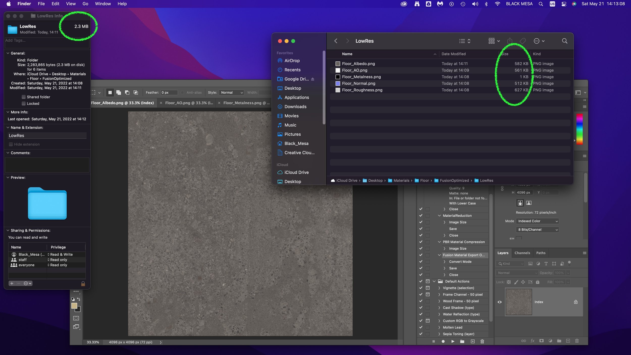
USDZ Texture Downsampling: Set to 1024px or up to 2048px (the
largest size acceptable for iOS QuickLook).
Update File Extension: Change the export file name extension
from .usdc to .usdz.
If no issues are encountered after export, you should be able to view your model in Augmented Reality on any iOS device. Open your exported file from iCloud, send it as an email, text, or AirDrop to another device to view.
Setting Up Xcode and Reality Composer:
The latest version of Xcode doesn't include Reality Composer, as Apple has shifted their focus to the Vision Pro. You can still access the Augmented Reality Tools for iOS devices, with some additional steps.
Step-by-Step Instructions:
Download the Latest Version of Xcode 14: Download from the provided
link: https://developer.apple.com/download/all/
NOTE: You'll need to create an Apple Developer Account (it's free) to access the above link, or using this direct link: https://download.developer.apple.com/Developer_Tools/Xcode_14.3.1/Xcode_14.3.1.xip
Extract and Rename The Older Version of Xcode: Rename Xcode.app to Xcode14.app and place it in your Applications folder.
Open Terminal on Your Mac.
Open the Applications Folder in Finder.
Drag the Xcode14 App into Terminal: This will automatically add its path.
Add to the Path: Next to the path, add: /Contents/MacOS/Xcode.
Full Command Example: The command will look like:
/Applications/Xcode14.app/Contents/MacOS/Xcode
Run the Command: Press Enter to run the command.
You should now have access to Reality Composer in Xcode. Click on the Xcode menu on the task bar, then click Open Developer Tool, and then click on Reality Composer.
Learn more about using Reality Composer here: https://developer.apple.com/documentation/realitykit/realitykit-reality-composer
Learn more about Apple Reality Kit and ARKit here: https://developer.apple.com/augmented-reality/tools/
BONUS: Generative AI and 3D
Tripo AI (https://www.tripo3d.ai/app) is an advanced generative AI tool that allows for both text-to-3D and image-to-3D model generation. This tool offers users an intuitive way to create complex 3D assets with minimal manual input, simply by describing what they need or providing a reference image.
Key features:
Text-to-3D and Image-to-3D Conversion: Users can input a detailed description or upload an image, and within seconds, the AI generates a draft model ready for refinement.
Prompt: "A pineapple-hedgehog with spiky fruit armor and leafy quills."
https://tripo3d.ai/preview?share=9a57357e-6262-469c-afb1-c7af74d92c93
Prompt: "A 1980s sci-fi robot stylized as a Nintendo NES product."
https://tripo3d.ai/preview?share=a08a55cd-9e66-48a5-be3d-85a26160e461
High-Speed Generation: Tripo’s AI processes are optimized for efficiency, allowing users to generate detailed models in a matter of seconds, ideal for prototyping or quick visualizations.
Customization Tools: After generating a model, users can adjust topology for increased details, or apply stylization, such as voxels.
Seamless Integration: Tripo3D supports a variety of export formats like .usdz .obj and .fbx, making it easy to import models into Blender and other software for further editing.
Generate full texture maps with PBRs: includes generation of PBR textures, adding even greater details beyond the geometry.
Automatic rigging and basic animations: Applies a basic animation rig to generated models and simple animations, such as a running character, to the model geometry.
Downsides:
Imprecise generation: just like AI image generators, results are unpredictable and often wrong.
Costs: Using this tool will require a membership plan, and has limited monthly credits, which limits usage.
CREDITS:
Thanks to all of these wonderful educators and content creators who continue to inform and inspire me throughout my 3D journey. Preparing this lecture required lots of time and consideration for how to condense what I’ve learned over the last five years into something I could demonstrate in under 2 hours. This wasn’t easy, but I had many fantastic resources to pull from.
If I’ve left anyone out, please leave a comment so I can include them here:
Ashley Deal and Raelynn O'Leary — CMU School of Design Faculty and Founding Partners at Dezudio http://www.dezudio.com
Phil Eichmiller — Principal Software Engineer at Autodesk: https://blogs.autodesk.com/community-journal/2022/04/26/meet-phil-eichmiller-principal-software-engineer/
YouTube Creators:
Reference Files:
Robot model created with Tripo AI
Robot model with corrected orientation
Note: Due to a bug, the robot walking animation doesn’t playback in QuickLook AR for iOS.