The Button
ABOUT
How might we leverage physical computing to improve everyday tasks, and what existing technologies can we adapt to improve a user experience? These questions formed the basis for an electronics prototyping project—this was also a chance to finally resolve a long-standing pet peeve of mine while receiving academic credit! 😀
The goals for this project included:
Developing a functional prototype, one which is built on both physical and digital components.
Programming an Arduino microcontroller to combine inputs and outputs (i.e., sensors and switches) to improve an everyday activity.
Designing a physical assembly to integrate components into a useable form.
Uniquely constrained by COVID-19 (e.g., the transition to remote/online learning, the closing of university facilities, businesses, and other institutions) I made several pivots throughout this process and discovered opportunities to take this prototype much further than its original intent.
This project was part of a series of studio-based learning assignments in Prototyping For Interaction Design, taught by Andrew Twigg at the School of Design at Carnegie Mellon University.

A functional prototype, this pair of devices can successfully record and reproduce IR codes over 2.4 GHz radio.

Problem Definition
A deep dive into infrared remote controls
“USER ERROR? NO, BAD DESIGN!”
—Don Norman, The Desing of Everyday Things
We all put up with a lot of “just okay” technology. It works, but it doesn’t delight. It is just okay. Close your eyes for a minute and think of the appliances, kiosks, remote controls, entertainment centers, desktop computers, and so-called “smart devices” that require bizarre and entirely unintuitive concessions. Sometimes this manifests as something benign, like needlessly repeating an action, or something that requires extra steps. In worst case scenarios this might mean that something doesn’t work as intended, or requires creative modifications to achieve a satisfactory result. I mention all of this because a core requirement for this project was to utilize a combination of sensors and switches to facilitate user interaction; and while this opened countless possibilities for interventions, I knew immediately what was at the top of my list: The needlessly frustrating Epson projector remote control experience.
For some background: I came home late one night from the graduate studio and found my girlfriend playing a frisbee golf video game—if you’ve never experienced the magic of playing Wii Sports Resort on a big screen, I highly recommend it—and I noticed that she had a small utility ladder set up in our living room, next to the couch. She told me that after struggling to turn the projector on and off via remote, it was actually more convenient for her to climb a ladder and press the power button on the projector itself.
What she needed wasn’t a better remote control. She just needed a better power button.
THE CURRENT STATE
[Feel free to scroll past to the next section “Sensors + Switches” if you want to just see what I made and how I made it. If you’re curious about why this intervention was necessary, read on.]
![[From the user manual of an Epson PowerLite Home Cinema 8350 projector.] Despite being a discrete function, describing the operation of powering on and off requires nearly two full pages of explanation and multiple illustrations.](https://images.squarespace-cdn.com/content/v1/5862ceee6a496371285c121b/1597975504954-4UABO8TN2SL2UFKCI4JA/Epson+Manual+2+pager.png)
[From the user manual of an Epson PowerLite Home Cinema 8350 projector.]
Despite being a discrete function, describing the operation of powering on and off requires nearly two full pages of explanation and multiple illustrations.
There are two practical methods for powering on the Epson PowerLite Home Cinema 8350 projector; there is a power button on the projector chassis itself (direct and local), as well as a power button on the remote control (indirect and remote). It might sound absurd to create a third method. Why do this, why add another layer of complexity?
The Epson Home Cinema projector is marketed as a home entertainment device and uses the common convention of an infrared remote control. This type of remote was originally designed to enable users to control their television sets from the comfort of their couches. This is generally a welcomed solution. These remotes require very little power, and can run for months at a time on a pair of AA batteries. Infrared sensors and LEDs are inexpensive, and the simple method of digital light pulses is an easy to implement mode of communication—it just works!
Kind of.
Sort of.
Most of the time?

The television set has evolved considerably from its humble CRT origins, but directional infrared remote control devices have been a common convention since the 1970s. This type of remote control (used with DVD, Blu-ray and other home entertainment devices) depends on a clear line-of-sight between the remote control’s IR emitter and the receiving sensor.
A few things can go wrong: the light source is relatively weak and it can easily be drowned out by natural sunlight or from artificial sources. Obstruction of the sensors can render the best remote controls useless. Another concern is feedback. Infrared light is not in the visible spectrum. Unless the remote control unit includes some other indicator (e.g., backlight LEDs that blink in response to key presses), a remote control’s operation is imperceptible. Nevertheless, this method is relatively hardy. The pulses of light can be received indirectly via reflection, and users do not usually need to be precise with pointing the remote at their intended device. With a fresh pair of batteries and reasonable placement, it’s a good solution.
So, what’s the problem? Why does this method not meet my basic needs?
The answer is simple: line-of-sight and placement.
The projector works best from only a few positions (see: “Choosing a Location”). Infrared digital pulse type remote controls are perceived as being fairly reliable in large part because their success is inextricably linked to the line-of-sight afforded by the intentional placement of the television itself. This is determined of course by the viewer’s desire to have an unobstructed view of the screen. This is a very straightforward relationship: If you can see the TV picture, then you can also control it.
![[From the user manual of an Epson PowerLite Home Cinema 8350 projector.] Illustrations showing some of the possible placement options; considering factors such as fan noise and heat dissipation, the ceiling and other above-head configurations …](https://images.squarespace-cdn.com/content/v1/5862ceee6a496371285c121b/1597976021916-RF3STBGQT51FY7LZP3LG/Epson+Manual+Placement.png)
[From the user manual of an Epson PowerLite Home Cinema 8350 projector.]
Illustrations showing some of the possible placement options; considering factors such as fan noise and heat dissipation, the ceiling and other above-head configurations are ideal.
For users, this experience is generally satisfying. They don’t need to think at all about things like digital pulses or hidden sensors; simply pointing the remote control at the screen establishes a clear line of sight for communication. But what happens when the picture is being projected from elsewhere? What happens when the screen is inert and physically separate from the image source? Without this relationship, line-of-sight breaks down.

Power and escape: After so many years of use, a product begins to change: the paint on these buttons slowly rubbed away, telling a subtle story about the actions that were most important or most frequent throughout its lifespan.
THE 80/20 RULE
Generally speaking, for any given interface roughly 80% of the user interactions involve only 20% of the controls. As a practical example, consider a long day of driving. Most of your interactions will involve the steering wheel and pedals. You will likely also use a few of the comfort controls (sound system and climate), but you most likely will not need or use every single control. Emergency blinkers, trunk release, seat adjustments, windows, mirrors, and other miscellaneous interactions are still important but rarely needed. The same is true for microwave ovens, dishwasher machines, elevator panels, Photoshop, and many other technologies.
With video projectors, this ratio is even more skewed. Typically, once properly setup and calibrated, a projector becomes an appliance: it is a thing to be turned on and off, but rarely is there a need to access other control. It is a device with one discrete function—to project a clear picture onto a flat surface. Let’s take a look at my remote (see image below) and consider this 80/20 rule. After nearly eight years of use, the pattern of wear can tell us a lot about how this device has been used.
As you can see pattern of wear, the Power and escape (abbreviated, “Esc”) buttons are the two most frequently used, but why? The Power button makes sense; to successfully make any other input with the remote, the projector must first be turned on, and any session involving other button pressing will ultimately be concluded with the power button being pressed two additional times (as show in the user manual): to avoid user error, the Epson projector requires a second confirmation press of the power button to initiate shutdown—the projector’s lamp requires a somewhat lengthly cool down-and warm-up phase when powering off and on, and this secondary confirmation helps to avoid accidentally initiating this cycle.
The Esc button’s story is a bit more complicated. This button is used for navigation purposes: pressing it exits from various on-screen menus. For users, this typically means it is the “go away, annoying menu pop-up that’s getting in the way of the movie I want to watch” button. It’s super useful and a well thought-out interaction, but it is also only ever needed when the rest of the remote control functions are being engaged.
If Epson had considered the overhead placement of their projectors as a factor, and centered their decisions from a user experience perspective, they would have seen the benefit to an omni directional remote control. If this projector and other brands/models designed their remote controls to operate by radio frequency to transmit commands, this project would be entirely unnecessary. Yes, this likely would have added some additional costs to unit production, and RF technology comes with its own set of unique drawbacks, but with thoughtful implementation it could be a better solution than their current IR remote controls.

Sensors + Switches
Prototyping with Arduino
PHYSICAL COMPUTING
Arduino is an open-source programmable microcontroller, designed to make prototyping interactive electronics easier than building customized digital and analog electronics from scratch. Arduino prototyping is modular, adaptable, and scalable. It uses industry standards (e.g., USB, C language compiler, etc.) and offers a high degree of compatibility with countless other devices. It is a dream come true for makers, tinkerers, professionals, artists, engineers, and educators; but it is not without its share of headache-inducing challenges. Open-source is great, but the quality of any given piece of code or other documentation varies. While it is possible to get help from a robust and vibrant online community, there is still a steep learning curve. Arduino operates on low voltage DC, and is somewhat forgiving to user error, but a basic knowledge of electronics and computer science are a minimum requirement.
COMPONENTS
There are other configurations and components that would work equally well or perhaps even better than what I have built, but if you are interested in reproducing this project, and would like to build one of your own (or build upon this design to do something else) here are the components I selected:
Schematic for both devices. (CLICK TO ENLARGE)
RoboGets, Nano microcontroller
Elegoo UNO R3 microcontroller
Deegoo-FPV NRF24L01+ 2.4GHz wireless RF transceiver Module (x2)
MXXGMYJ 38KHz IR receiver (2H24075A) 38KHz IR emitter (2H24073A) module kit
NOYITO 12mm metal button switch with blue LED power symbol
JXMOX USB C to Mini USB 2.0 Adapter
LED (blue, generic)
Gikfun mini solderable breadboard (x2)
120 ohm resistor
220 ohm resistor
Socket head screw, M1.4 x 0.30 mm thread, 8 mm long (x 8)
Button head hex drive screw, M1.6 x 0.40 mm thread, 10mm long (x 8)
Button head hex drive screw, M3 x 0.50 mm thread, 22mm long (x 2)
RESOURCES
HARDWARE+SOFTWARE
As mentioned earlier, Arduino is an open-source platform. I didn’t need to build from scratch because other people have done most of the heavy lifting. I’m able to benefit from the hard work, and the experimentation from other makers, coders, and tinkerers. Most of the code used in this project was sourced and modified from this post:
I also reviewed several other projects and resources to get a better sense of how I might bridge the gap between IR and RF communication:
https://learn.sparkfun.com/tutorials/ir-communication/all
https://www.electroschematics.com/ir-decoder-encoder-part-2-diy-38-khz-irtr-module/
https://learn.adafruit.com/using-an-infrared-library/hardware-needed
https://www.sparkfun.com/datasheets/Components/nRF24L01_prelim_prod_spec_1_2.pdf (PDF Warning)
https://www.deviceplus.com/arduino/nrf24l01-rf-module-tutorial/
https://forum.arduino.cc/index.php?topic=421081.0
https://howtomechatronics.com/tutorials/arduino/arduino-wireless-communication-nrf24l01-tutorial/
INFRARED REMOTE CONTROL CODE REPEATER
(NOTE: to use the code provided below, you will also need to have the appropriate libraries loaded.)
Wiring diagram for the infrared remote repeater and radio-frequency receiver. (CLICK TO ENLARGE)
#include <SPI.h>
#include <nRF24L01.h>
#include <RF24.h>
#include <IRLibAll.h>
RF24 radio(9, 10); // CE, CSN
const byte address[6] = "00001";
boolean button_state = 0;
int led_pin = 3;
IRsend mySender;
void setup() {
  pinMode(6, OUTPUT);
  Serial.begin(9600);
  radio.begin();
  radio.openReadingPipe(0, address);   //Setting the address at which we will receive the data
  radio.setPALevel(RF24_PA_MIN);       //You can set this as minimum or maximum depending on the distance between the transmitter and receiver.
  radio.startListening();              //This sets the module as receiver
}
void loop()
{
  if (radio.available())              //Looking for the data.
  {
    char text[32] = "";                 //Saving the incoming data
    radio.read(&text, sizeof(text));    //Reading the data
    radio.read(&button_state, sizeof(button_state));    //Reading the data
    if (button_state == HIGH)
    {
      digitalWrite(6, HIGH);
      Serial.println(text);             //Arduino Remote On/Off button code
      mySender.send(NEC, 0xc1aa09f6);
    }
    else
    {
      digitalWrite(6, LOW);
      Serial.println(text);
    }
  }
  delay(500);
}
REMOTE POWER BUTTON AND INFRARED REMOTE CONTROL CODE READER

Wiring diagram for the remote power button unit. (CLICK TO ENLARGE)
#include <SPI.h>
#include <nRF24L01.h>
#include <RF24.h>
#include <IRremote.h>
RF24 radio(9, 10); // CE, CSN
const int RECV_PIN = 2;
IRrecv irrecv(RECV_PIN);
decode_results results;
const byte address[6] = "00001";     //Byte of array representing the address. This is the address where we will send the data. This should be same on the receiving side.
int button_pin = 7;
boolean button_state = 0;
void setup() {
  pinMode(button_pin, INPUT);
  Serial.begin(9600);
  irrecv.enableIRIn();
  irrecv.blink13(true);
  radio.begin();                  //Starting the Wireless communication
  radio.openWritingPipe(address); //Setting the address where we will send the data
  radio.setPALevel(RF24_PA_MIN);  //You can set it as minimum or maximum depending on the distance between the transmitter and receiver.
  radio.stopListening();          //This sets the module as transmitter
}
void loop()
{
  button_state = digitalRead(button_pin);
  if (button_state == HIGH)
  {
    const char text[] = "Your Button State is HIGH";
    radio.write(&text, sizeof(text));                  //Sending the message to receiver
  }
  else
  {
    const char text[] = "Your Button State is LOW";
    radio.write(&text, sizeof(text));                  //Sending the message to receiver
  }
  radio.write(&button_state, sizeof(button_state));  //Sending the message to receiver
  delay(1000);
    if (irrecv.decode(&results)) {
    Serial.println(results.value, HEX);
    irrecv.resume();
    // based on code downloaded from: https://create.arduino.cc/projecthub/muhammad-aqib/nrf24l01-interfacing-with-arduino-wireless-communication-0c13d4
  }
}
IS THIS THING ON? …
As you can see, the RF to IR works very well. It is responsive, and pressing the button on one controller results in an immediate input to the projector’s IR sensor. Having resolved the desired function, I then needed to think about the form of the device and how I might improve the user experience of mushy remote control buttons with intolerant line of sight limitations.
Assembly Design
Ideation and pivot to remote work
IDEATION
The electronics and code work. The RF transmitter also detects, decodes, and outputs digital IR remote pulses when connected via USB (read out through the serial monitor in Arduino App or terminal console). This device can easily be adapted to relay other communications, including the potential for bi-directional IR-RF communication. It is scalable, and can be customized for countless other applications. To fully realize this potential, it was also necessary to develop a practical pair of enclosures for both devices.
Originally, I intended to only build a basic structure from laser-cut 3mm acrylic sheets. I’ve had some success designing 3D assemblies from laser-cut sheets before, and was especially interested in the potential for a top-down design workflow to conform measured dimension of components to an eventually tailor-made assembly. I began this process with simple sketches, followed by designs in Autodesk Fusion 360, and then simple paper prototypes to evaluate form off-screen.

Sketch of initial assembly concept: dimensions based on laser-cut 3mm acrylic sheet enclosure for Arduino Uno.
First iteration of laser-cut assembly.

Sketch of 2nd generation assembly.
Rendering
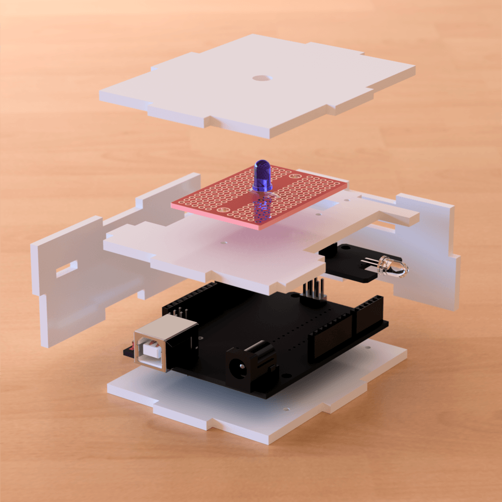
In response to COVID-19, the university made the difficult decision to shutdown and transition to online/remote classes. This also meant that facilities (including wood shops and maker spaces) were no longer available to students. Given that this project was part of a studio-based course, it was incredibly frustrating to think of new ways to work without the benefit of institutional and material support. Nevertheless, I embraced the challenge and resolved to produce 3D renderings as a proof of concept and as a substitute for the physical assembly I’d intended to build. Since I was no longer constrained by fabrication techniques, I decided to design something more compelling than a simple box. The results of this were a pair of devices with simple two-part assemblies with rotational lock and a single screw at the base. The layout of the internal components were arranged to maximize the function of IR and RF, while also providing users with visual feedback: a single blue LED in the IR transmitter assembly (seen on the right side of the image below) with a diffusing material to scatter IR pulses in an omnidirectional manner. The RF transmitter (seen on the left) is a solid and opaque device with a window that allows it detect and read the IR pulses from a remote control.

Rendering of finalized assembly designs (made with Autodesk Fusion 360).
I’ve been working with Fusion 360 since 2018, and one of the things that really appealed to me, right from the beginning, was the rendering workspace. Fusion 360 offers an impressive and easy to use ray tracing rendering interface. The physically based materials library is massive and allows users to select from both local and cloud-based options. Additionally, users can customize materials: adjusting things like surface roughness, subsurface and transparency settings, and emissive properties. You can even do your renderings in the cloud—saving you lots of time on computationally intense and laptop-roasting CPU loads. The net result is a photorealistic image that really brings your design to life.
Well… almost.
Fabrication
FROM SCREEN TO OBJECT
Fabrication
From screen to object

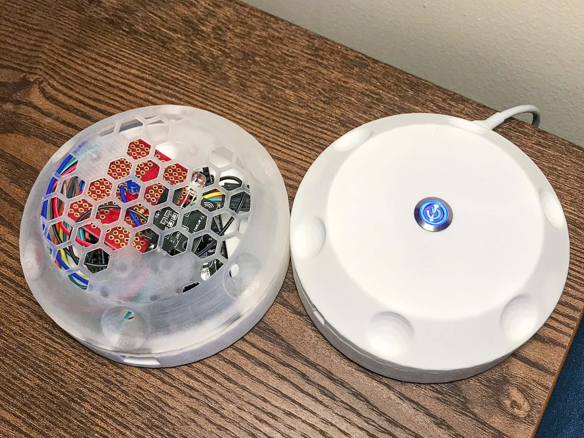
Interaction and utility are central aspects to this project, and not having a physical artifact (to evaluate my design decisions or make additional improvements) was incredibly frustrating. I began to explore options for 3D printing services and found Shapeways to be fairly reliable (although a bit pricey). I decided to take a chance, but one immediate concern I had when ordering was the appearance of the components after importing. Looking at the image on the right, you may have noticed the low-poly, blocky surface. Not knowing how Shapeways was handling the data a sent (an .OBJ wavefront format), I considered the possibility that this was just how it renders on their website (a performance optimization). The only way I could know for sure was to order the parts and see whatever they shipped to me.
The results of this experiment were mixed. It turns out that the low-poly conversion applied to the 3D print also. I’ve since learned that the best way to avoid this is to do the conversion in Fusion 360. Converting T-spline to high triangle count meshes will ensure preservation of rounded edges. Additionally, the tolerances are roughly sub-millimeter, but they are not perfect. This meant that many of the components did not mount properly with the screws I ordered from McMaster-Carr. In some cases, I simply drilled out the holes, in other cases I would need a larger screw—something not worth the cost of exploring.
I was still able to build a working assembly and the results are very satisfying. During this public health crisis, I’m staying home and I appreciate having a reliable and responsive on/off switch for my projector. When I spin up a laserdisc or stream a show on Netflix, it’s nice to have access to a big screen on demand—I miss going to movie theaters, but I’ve also gotten really good at making popcorn. When my girlfriend wants to play DDR on the Nintendo Wii or destroy me at trivia, every step is simple and straightforward.
It just works.
